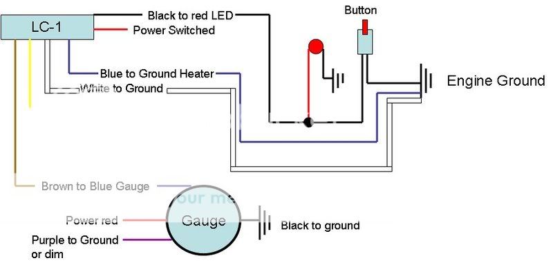
The most important concern of this installation is a decent source for a ground.
The following is taken from
http://www.innovatemotorsports.com/resources/grounding.php:
Application Note: Electrical Grounding Concerns
The electrical environment inside a car provides unique challenges, combining high voltages and currents, low-voltage signals, convoluted signal paths, and variable conditions (i.e., fans turning on and off, or starter cranking).
When using precision electronics, it is important for ALL electronics to share a common ground. Remember that “Ground” is more than just the return path for any circuit- it is also the reference against which any voltage is measured.
Since it is not always practical to ground every device to the exact same location, here are some tips on grounding:
1. The BEST grounding scheme is all grounds (i.e., ECU, Gauges, LC1 heater, LC1 system, etc.) SOLDERED into a single lug and bolted to the engine block.
2. The next best is all grounds attached to the same source, as close as possible, but on separate lugs. This is because even the corrosion between lugs can create ground offset and noise. Incidentally, this is why many ECUs have separate ground wires for injectors vs. ECU system ground- separating high voltages and low voltages reduces noise.
3. Grounding to the engine block is usually better than grounding to the frame.
4. Grounding a gauge to the radio is usually bad- ground offset can vary with volume.
5. Grounding to an ECU housing is generally not optimal- housings are strapped to the frame for shielding, but not necessarily grounded.
6. One of the WORST things to do is to ground most of your electronics to one place (i.e. the engine block), but ground one device somewhere else (i.e., the frame). Not only can this result in ground offsets, it can also create a “path of least resistance” for high currents THROUGH a low-current device. This can result in melted wires and vaporized diodes, when, for example, starter currents flow through gauges.
As stated above I chose to have all grounds (i.e., ECU, Gauges, LC1 heater, LC1 system, etc.) SOLDERED into a single lug and bolted to the engine block. Grounding to the engine is much better than grounding to the frame.
To achieve this, I took probably about 10 feet of 18 gauge wire and stripped on end of it. I then crimped and soldered a loop connector at the end of the wire. I then took heat shrink tubing and applied heat with a heat gun to shrink the tubing. This prevents moisture and material from entering and corroding the wire.
One the rear of the drivers side head, there is a stud bolt in the upper corner of the head. You will see some wires already grounded there. These are fastened on the stud bolt by a 10mm nut. Remove the top 10mm nut and fasten the ground wire with the loop connection onto this stud bolt. Then put the 10mm nut back on stud bolt and tighten.
You have no created a single lug bolted to the engine block.
You will see my 18 gauge ground wire as the yellow wire depicted in the below picture. Also, there is a purple and black wire next to it. That is one of the already preexisting ground wire.
Next I removed this cover to have better access to the rubber plug where all the wires enter into the vehicle from the engine bay.
This is the plug where some wires entire from the engine bay through the firewall into the vehicle.
To remove just squeeze and pull outward. You do not want to pull hard and pull the wires with excessive force.
Next I took and exacto knife and made a small incision into the tape on both ends of the plug and removed a small portion of the tape.
I then made a small incision in the rubber plug to make the hole slightly larger in diameter to accommodate the LC-1 wire harness, 2 terminator plugs, and the ground wire.


